Build your first model
Create a model, organize its content, and present a small system structure in a Diagram. Choose a system you want to describe and use names appropriate to that system.
Before you begin
You need a running SES Modeler installation. Follow Installation if necessary, or obtain your installation’s web address.
The Model Repository can be empty. You will create the content used in this walkthrough. Screenshots illustrate the controls using a separate model; matching its names or structure is unnecessary.
1. Create the model
- Open SES Modeler. If the landing page appears, choose Enter SES Modeler.
- If the Welcome screen appears, enter your Display name and choose Enter workspace.
- In the Model Repository, choose Create New Model.
- Enter a Model name for your project. Optionally add a description and icon.
- Choose Create Model.
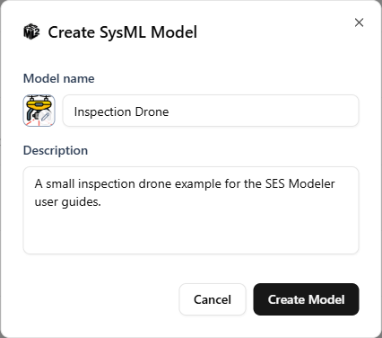
The workspace opens with a package bearing your model’s name and a starter view named General.
Choose Model Browser in the left activity rail if the tree is hidden. Expand the top model entry to find its package. Use the package row, rather than the top model entry, when creating content in the next step.
Check: your model is open, and its root package is visible.
2. Create a package and a system definition
- Open the root package’s actions menu.
- Choose Create Element → package.
- Enter a name describing the content it will organize and press Enter.
- Open that new package’s actions menu and choose Create Element → part def.
- Enter the name of the system you want to describe and press Enter.
A package organizes elements. A part definition describes a reusable kind of system or component.
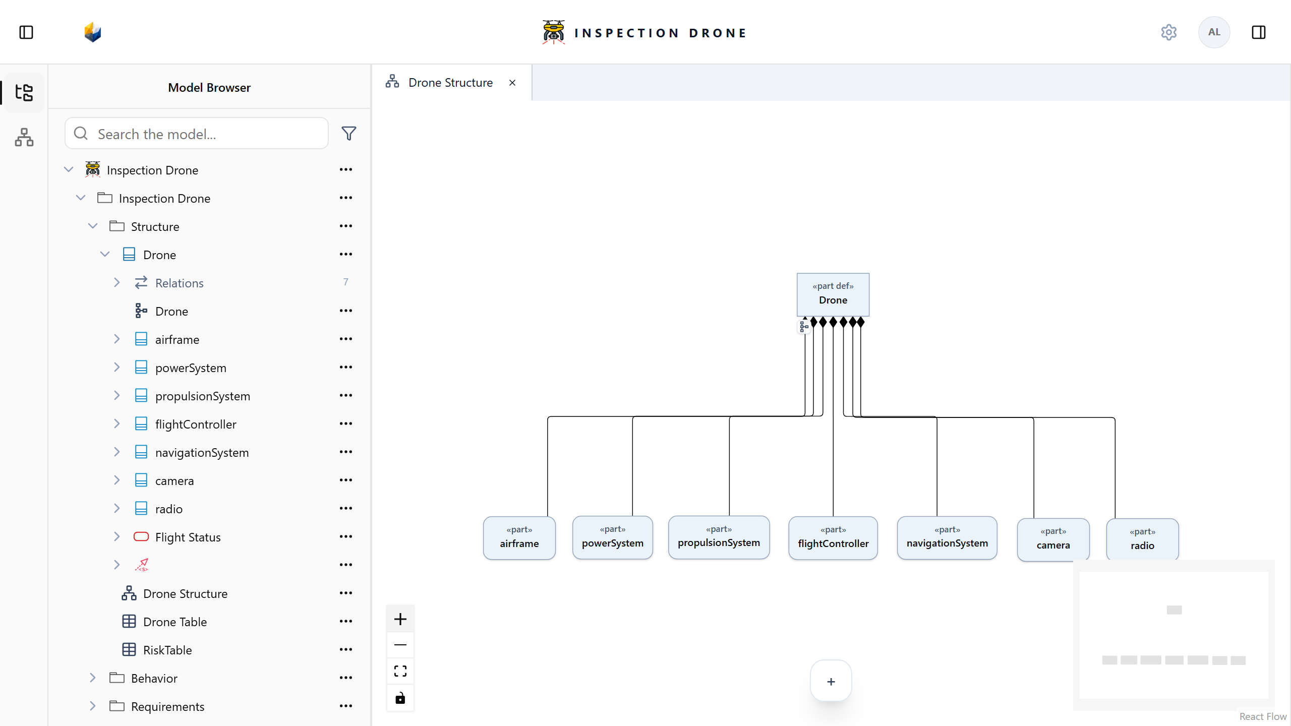
Check: the package owns your new part definition.
3. Add the system’s parts
- Open your system definition’s actions menu and choose Create Element → part.
- Enter the name of a component or subsystem and press Enter.
- Repeat from the system definition’s menu for the other parts you want to include.
Check: expand the definition to see the parts you created beneath it. Sibling parts appear at the same indentation level.
To describe a component’s own composition, open that part’s actions menu and create its child parts there. The owner you choose determines where each new element belongs.
4. Set a component count
When one named part represents several instances:
- Select that part in the Model Browser.
- In its inspector, choose Edit multiplicity.
- Set Range to Exact count.
- Enter the required Count and choose Save.
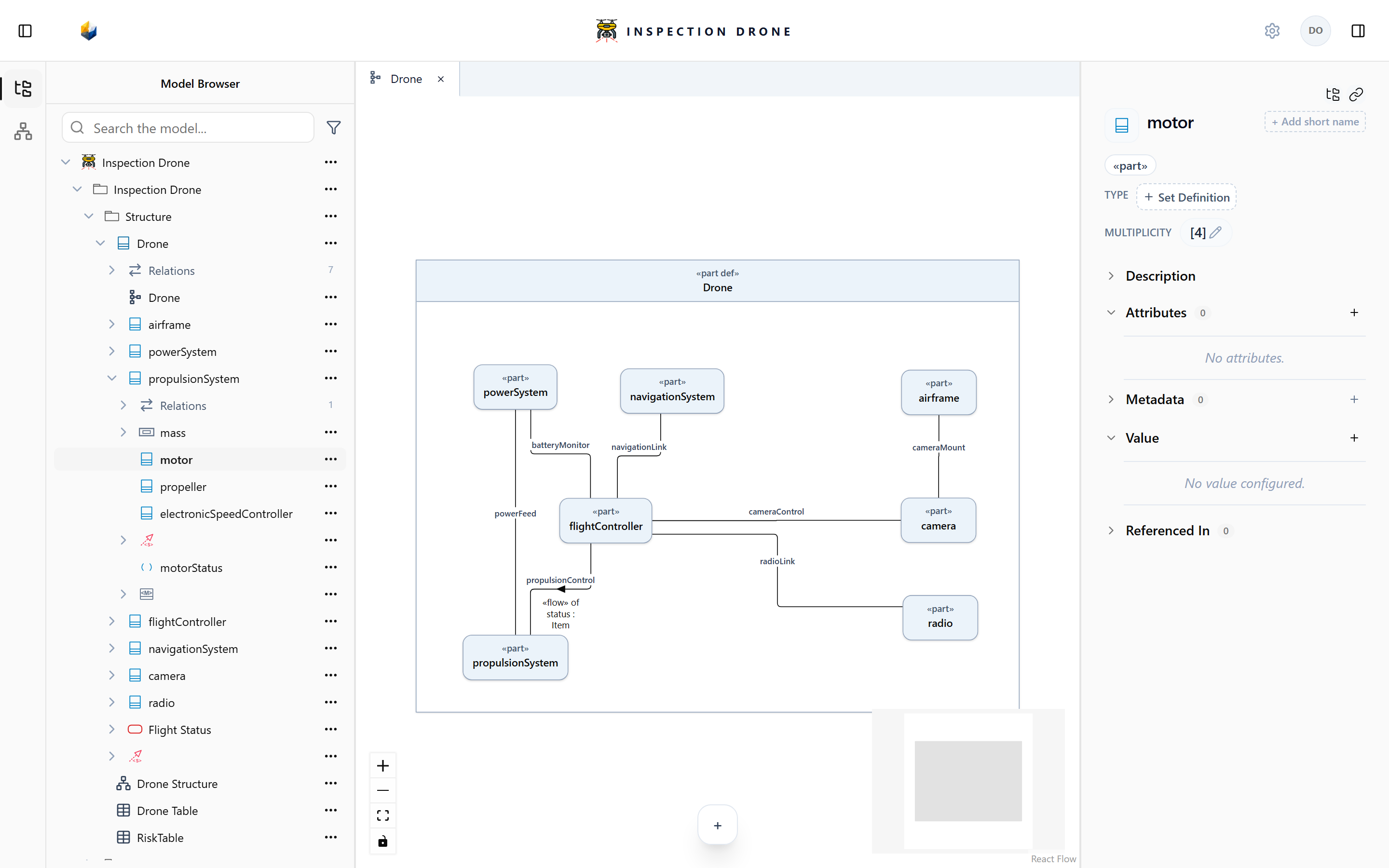
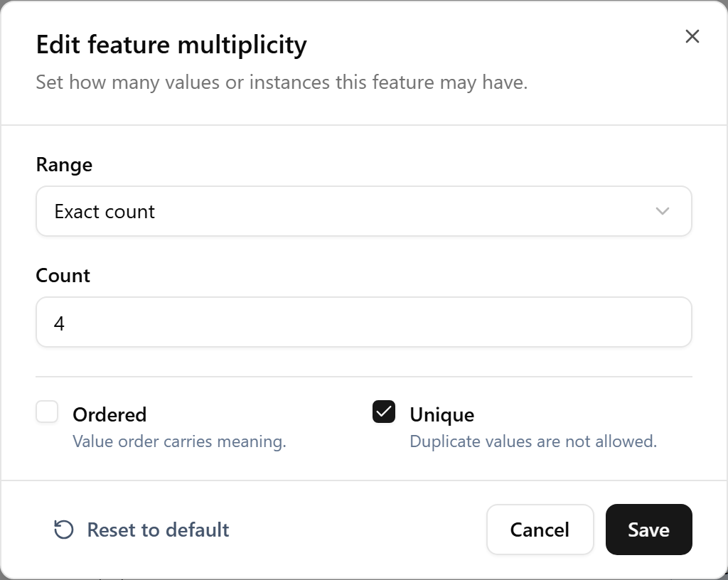
Check: the selected part’s inspector shows your count. Multiplicity records several instances of one role without requiring separately named model elements for each instance.
5. Present the parts in a Diagram
- Open your system definition’s actions menu and choose Create View → InterconnectionView.
- Enter a name for the view and press Enter.
- If its editor is closed, double-click the view in the Model Browser.
- Expand the system definition so its parts are visible.
- Drag each part you want to present into the system frame in the Diagram.
- Arrange the presentations so their names are readable. Use Fit View if needed.
Creating a view does not automatically populate it. Dragging an existing part creates a presentation of that element.
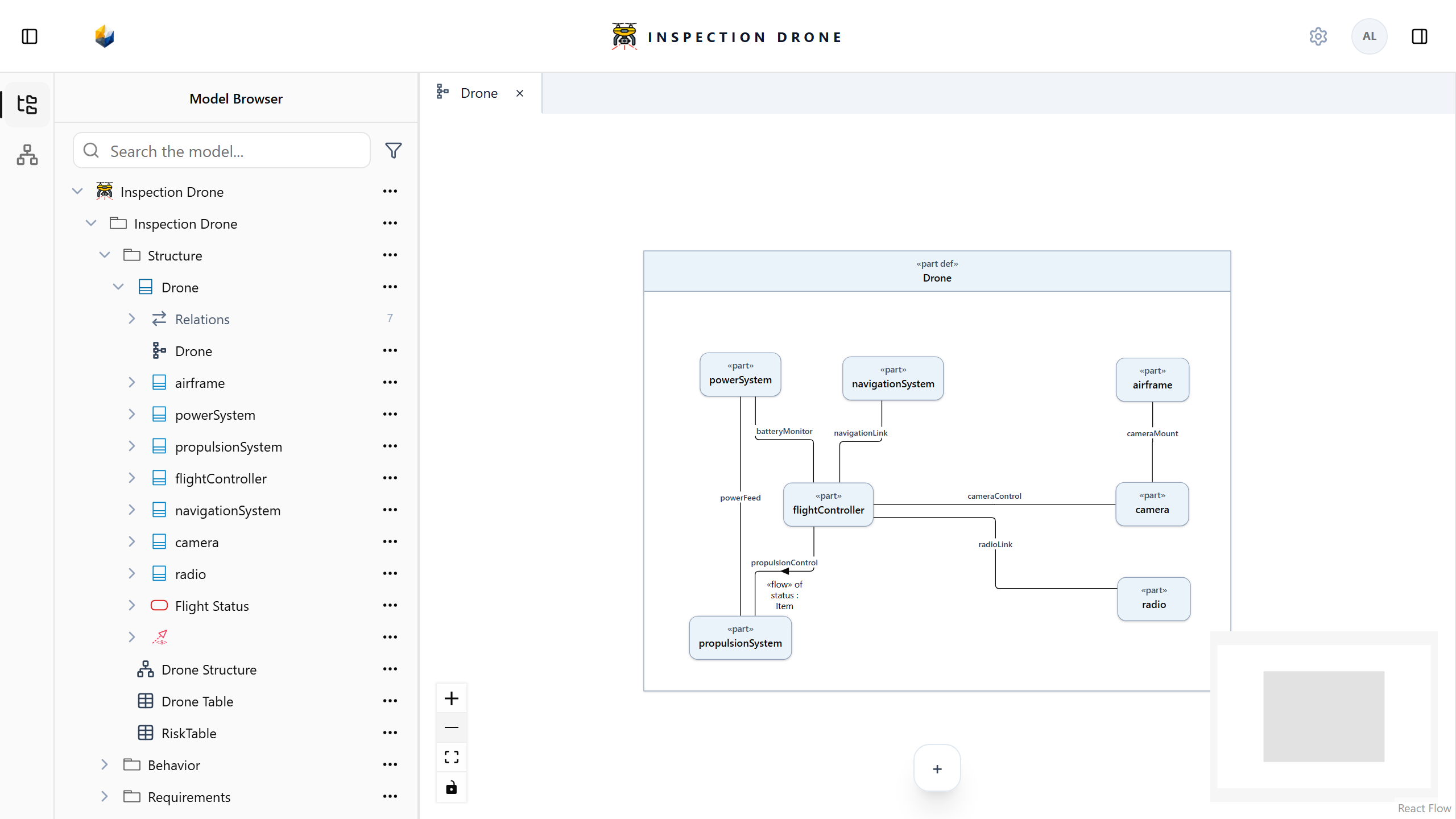
Check: the frame presents the parts you added. Select a presentation to inspect the same model element shown in the tree.
6. Explain the system
- Select your system definition in the Model Browser.
- Expand Description and choose Add documentation.
- Explain the system’s purpose and the responsibilities of its main parts.
- Finish using the editor’s checkmark.
Check: selecting the definition again shows the explanation you saved.
Check your result
Your model should contain the package, definition, and parts you created. Its Diagram should present the intended parts, and the inspector should retain your documentation and any multiplicity changes.
The screenshot’s model hierarchy, extra views, connections, and values are not completion criteria for this walkthrough.
If you get stuck
Cannot find an element? Choose Model Browser, reopen the sidebar if collapsed, clear search and type filters, then expand the owner you used.
Creation kind missing? Use a package’s menu for part def, a system definition’s menu for its part elements, and that definition’s menu for InterconnectionView. If the view kind remains unavailable, check view availability and the installation’s libraries.
Empty Diagram? Drag your existing parts from the Model Browser into the frame.
Version conflict? Keep any text you need, cancel the draft, reload, and retry against the refreshed model.
Continue with Understand the workspace.