Diagrams
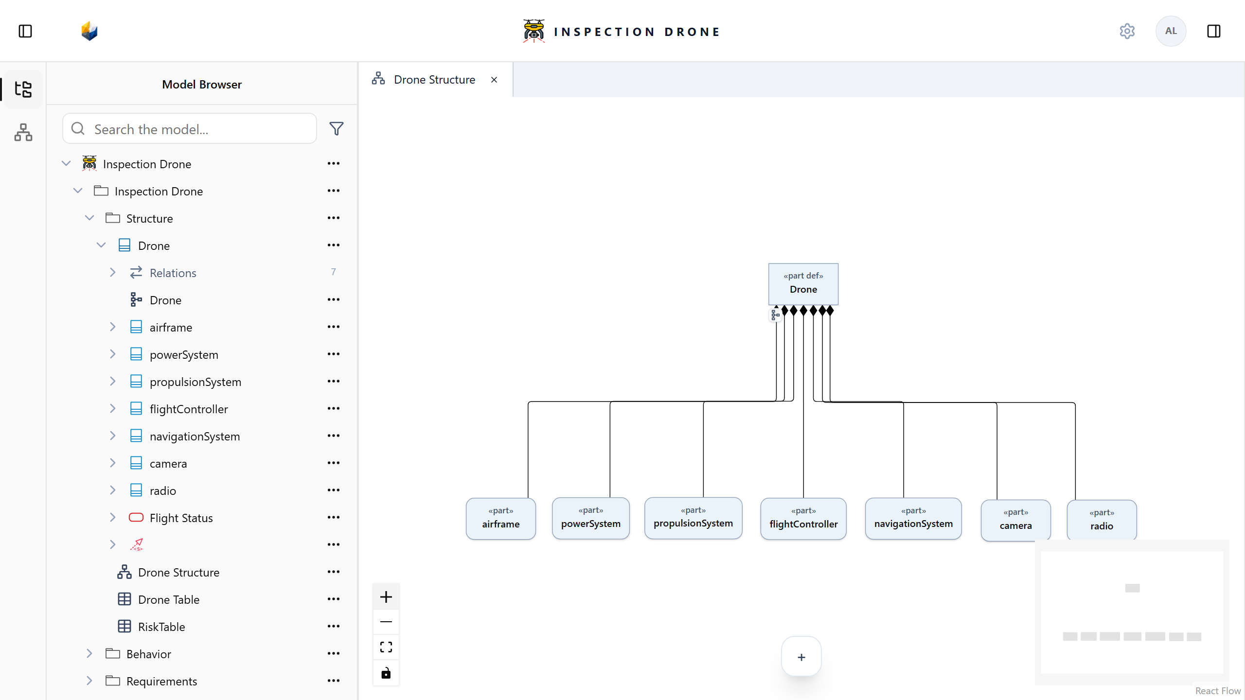
A Diagram presents model elements and relationships visually. Choose a representation suited to the task: structure, interconnections, actions, states, or use cases.
What you need
Use an editable model with elements to present. If necessary, create them in the Model Browser.
Create a view lists view kinds and their appropriate owners. Select a static view when you need to edit its presentations manually.
Populate an interconnection view
- Open the system definition’s actions menu and choose Create View → InterconnectionView.
- Name the view and open it.
- Expand the definition in the Model Browser.
- Drag the existing parts you want to present into the system frame.
- Arrange their presentations to make the design readable.
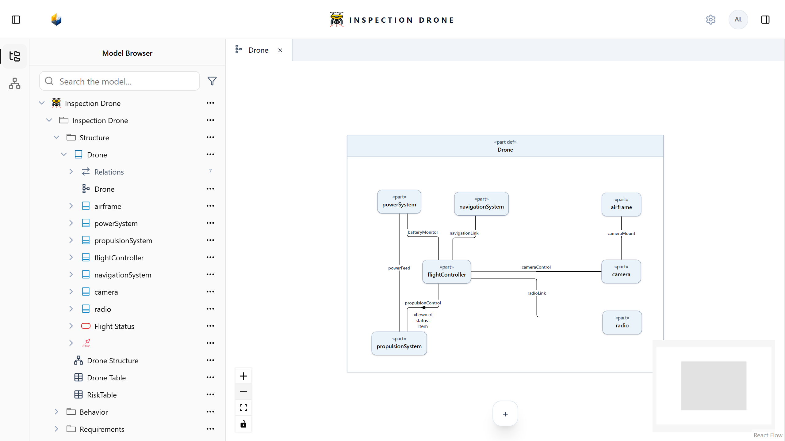
Check: selecting a presentation opens the inspector for that same model element. Dragging an existing element adds a presentation; use Create or the Model Browser when you intend to create a new element.
A connection line must represent an actual relationship. See Connections and interfaces to create one.
Arrange and navigate
Use Select to select and move presentations, and Hand tool to pan without moving them. Zoom In, Zoom Out, and Fit View change the visible area.
Close a sidebar when you need more room. For use case views, fitting considers both the system boundary and actors; use panning to adjust their position in the viewport.
Remove a presentation or element
Read the offered action before confirming removal. Removing a presentation changes the view; deleting its underlying element can affect other views that refer to it.
If a creation or editing control is missing, check the selected view kind, node kind, and model editability. A dynamic Diagram computes its presentations and is read-only; change its selection configuration or model content to change what it presents.